Formula SAE Control Arm Redesign
Redesign Motivation
At the Formula SAE Michigan Competition in 2022, CU Boulder Racing brought our second ever car CB2 and we were unable to pass the brake test. Through hours of bleedings the brakes and a total 26 attempts we were never able to get all 4 wheels to lock at the same time.
It was determined the brake our brake hardline geometry was a main component that made achieving the required pressure to lock all four wheels. The issue was we routed the hardlines over our pull rod damper covers, this created a high point in our system that made getting air bubbles out of the system very difficult and time consuming.
The fix for this would be to move to direct link push rod set up allowing for a completely flat floor eliminating the high point in the braking system.
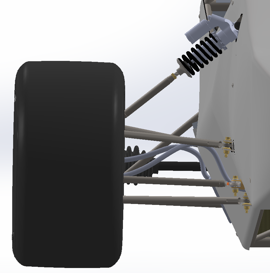
CB2 pull rod geometry with damper covers
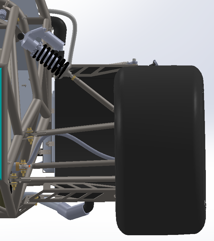
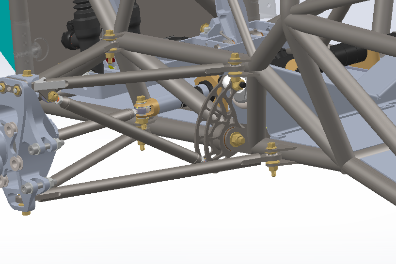
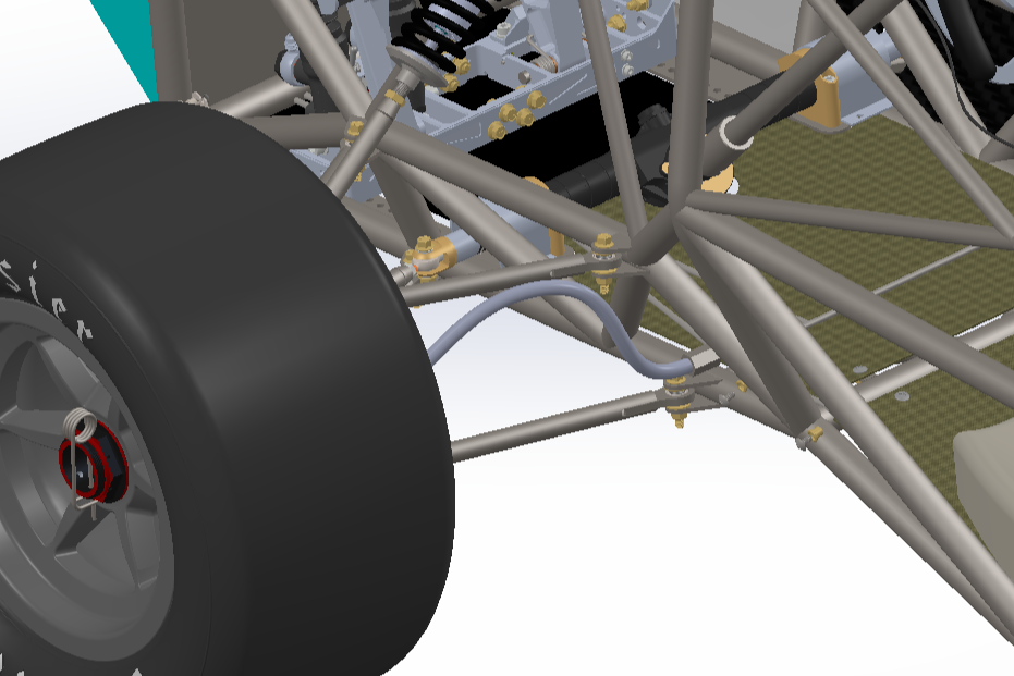
CB3 push rod geometry with flat floor
Suspension Geometry Changes
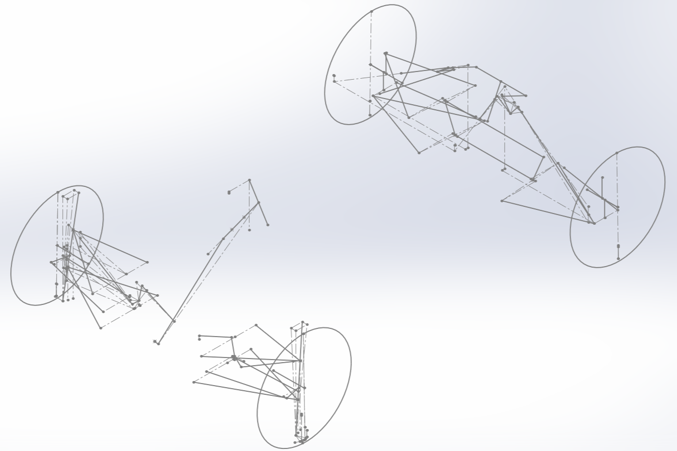
CB2 suspension geometry
For CB4 the suspension geometry and movement ratios where determined by our chassis lead based on handing targets the team had set. The suspension geometry sets all the connection points for all components thus giving the hard points the control arms must be designed to connect to. The suspension geometry and mainly carried over from the CB2 car with the exception of the front damper location. So the rear control arms did not need to be modified, but the fronts would have to be redesigned to fit the new geometry and clearances required.
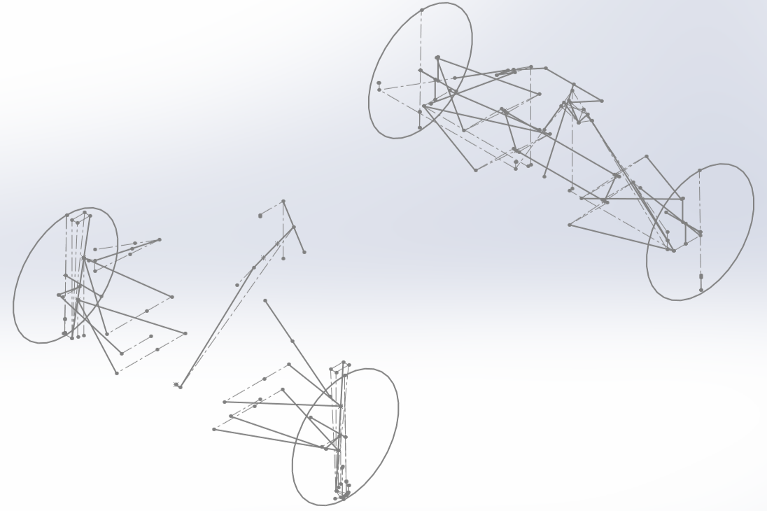
CB3 suspension geometry
Design
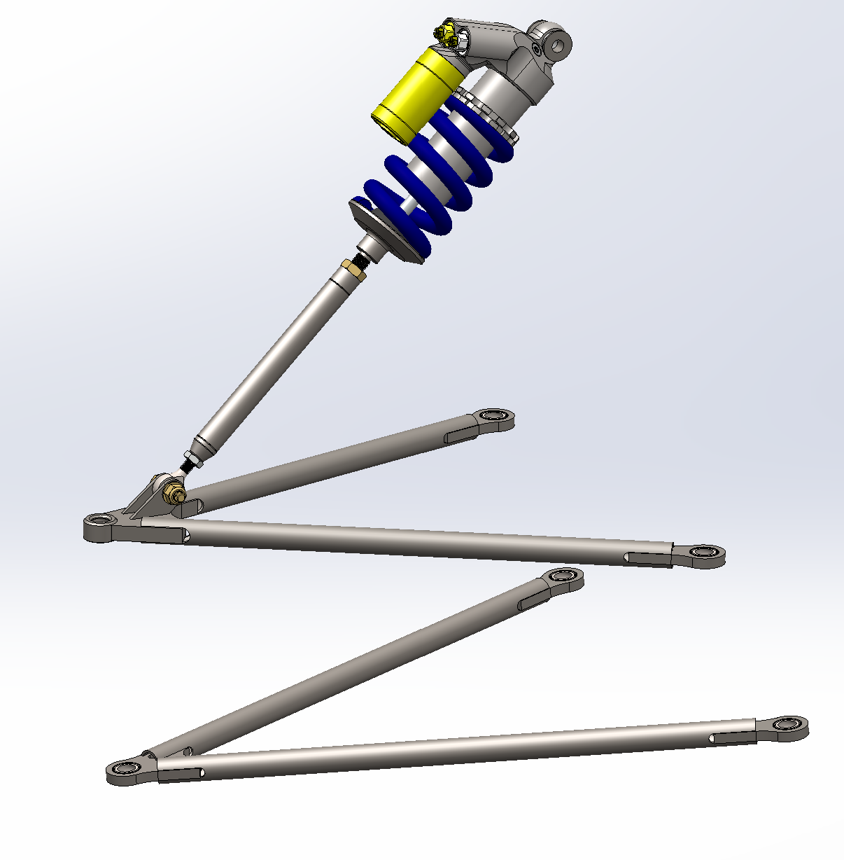
The change from pull rod to push rod required some changes to where the damper would be mounted in reference to the control arm. Originally it was believed we could simply flip the previous year’s design upside down so the mounting tabs would be on the top surface of the upper control arm. This was quickly dismissed because of clearance issues to the wheel. The previous design had a much smaller angle for pull rod compared to the angle required for our desired relative motion of the spring and mounting location on the frame.
CB2 pull rod clearance to wheel
In order to achieve this design the the mounting tabs would have to be moved farther inboard on the mounting plate. By doing so the force acting on the road through the push rod to the chassis was now also farther inboard putting the control arms in bending. The unequal length double wishbone control arm design ideally only experiences forces of tension and compression. In order to deal the mounting tabs more inboard the upper control arm tube thickness was increased from .058 to .065 inches.
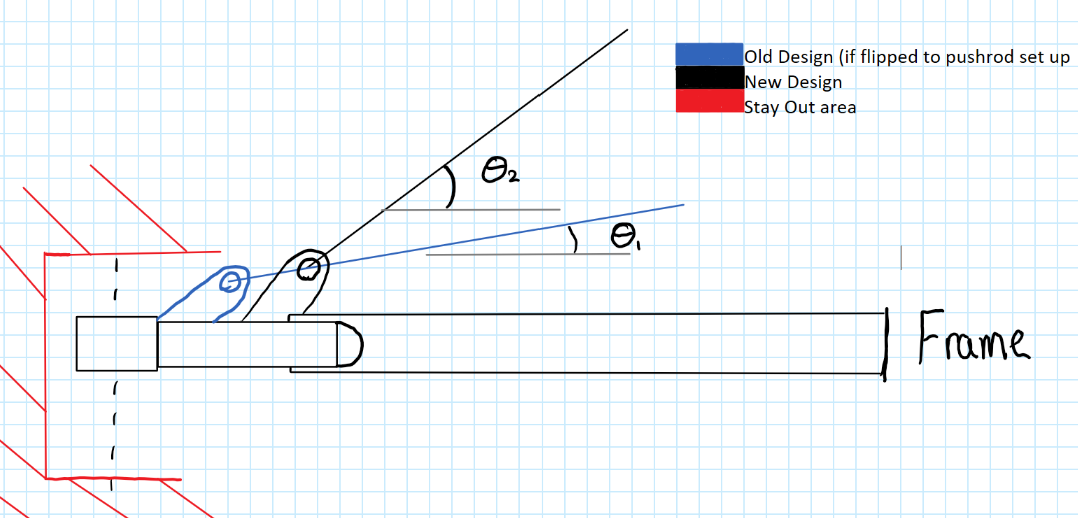
Hand sketch illustrating different pushrod angles
CB3 push rod clearance to wheel
Analysis
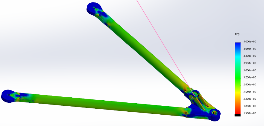
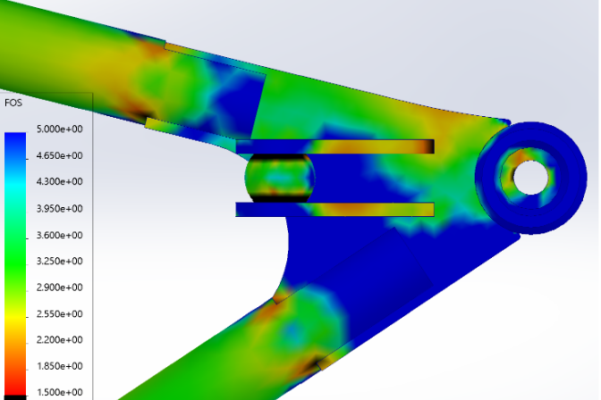
To design the control arms the forces which they will be experiencing must be calculated. For our team we got our maximum tire forces from the Pajecka Tire Equation for our specific tires then we are able to create our six different load cases. These load cases include maximum acceleration, maximum braking, corner entry, corner exit, maximum corner, and a 5G bump cases. From there we use a code that former team member created that essentially calculates the forces in the X,Y, and Z direction for point. It does this by taking the distances from the tire contact patch and connection locations to give distance vectors which can be used in the force solver equations. These forces can then be put into Finite Element Analysis and then solve for max stress, factor of safety, and deformation.
These calculations are also double checked with simplified hand calculations where the control arm is treated as a 3 force member then wall thickness accounted for finding the maximum stress in the tubes. Buckling is also double checked using hand calculations where the maximum compressive force is used.
Final Results
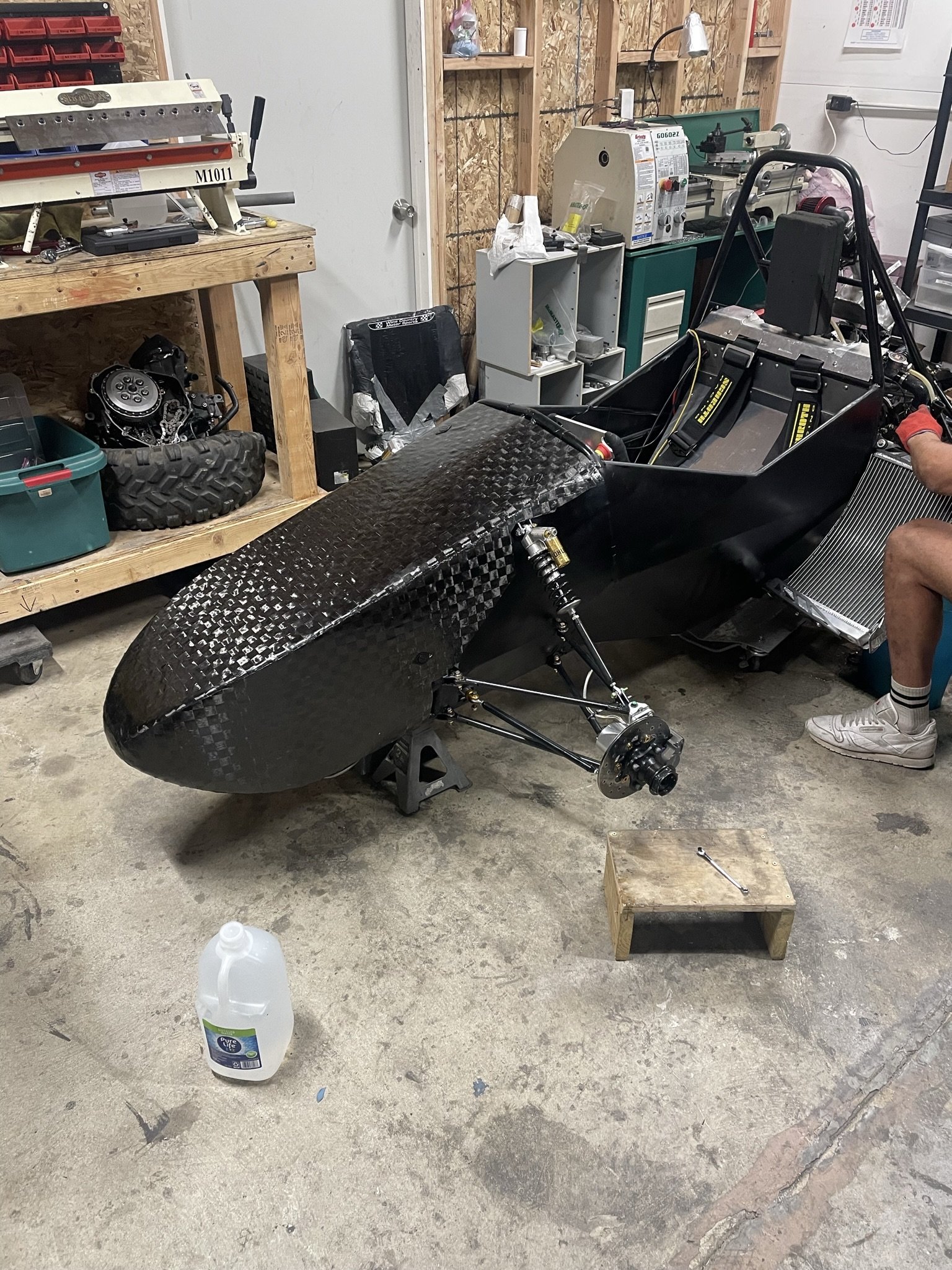
The Front Control Arms redesign gave the desired result of freeing up space in the interior of the chassis with the simply direct linkage design. This change coupled with some better brake bleeding techniques resulted in the team passing the brake test for the first time in team history allowing us to run in the Dynamic Events of the Formula SAE Michigan competition. This geometry and design would be reused for the next year before moving to the teams current design of outboard vertically mounted rockers.